Types of shaft alignment methods:
- Visual Line-Up
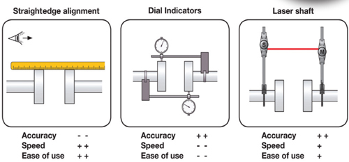
- Straightedge/Feeler Gauge
- Rim and Face
- Cross Dial
- Reverse Dial
- Laser
Visual Line-Up
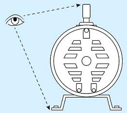
The visual line-up method is the most common method of alignment. Used in initial installations, visual line-up allows technicians to analyze the working conditions and feasibility of installation.
Straightedge/Feeler Gauge

Straightedges are used to determine the offset between coupling halves. Corrections are made under all four of the machines feet. Feeler gauges or taper gauges measure the gap between coupling halves at the bottom and top of the coupling.
Rim and Face
This method is similar in principle to using a straightedge and feeler gauge, but more accurate since dial indicators are used. The rim reading measures the offset between the coupling halves. The face reading measures the angular difference between the faces of the coupling. Changes are calculated with the same formula as the straightedge/feeler gauge method.

Advantages:
- Used when only one shaft can be rotated.
- Given the correct precautions, precision alignment is attainable with this method.
Disadvantages:
- End float affects face reading.
- Indicator bracket (bar) sag affects readings.
- Eccentric, skewed couplings or damaged surfaces will cause errors.
- Fixture looseness causes errors.
- Indicator stems not perpendicular to shaft causes errors.
The indicators should be checked to ensure that:
- The plungers are level, parallel to shafts, and depressed about half their total travel.
- The indicators are same distance from the shaft axis and exactly opposite each other when two indicators are used.
- The contact points are midway between coupling halves in the axial direction.
If sag-free brackets are not available, sag greater than .001 inch must be compensated for.
Cross Dial
This method uses two dial indicators mounted exactly 180 apart to take shaft-to-shaft readings. Both parallel and angular misalignment may be compensated for at the same time. This method allows the couplings to remain attached, as the shafts must move together.

Advantages:
- Very accurate method of using dial indicators
- Easy and fast to use
- Simple
- Graphical calculations for misalignment are non-technical
- Computer or pocket calculators can also be used
Sources of error are:
- Indicator stems must be perpendicular to the shaft
- Looseness
- Indicator bracket (bar)sag
- Coupling backlash
- Extreme axial float
- Indicators that are not exactly opposite each other.
Reverse Dial
This method uses two dial indicators that take shaft-to-shaft readings and is almost the same as the cross dial method, except that the indicators are in the same plane with each other. Both the offset and angularity are combined in the alignment calculation. This method determines the misalignment by taking two rim readings at different points along the shaft.

Advantages:
- Most accurate method of using dial indicators
- Easy and fast to use
- Simple
- Graphical calculations for misalignment are non-technical
- Computer or pocket calculators can also be used
- Requires only 180 rotation
Sources of error are:
- Indicator stems not perpendicular to the shaft
- Looseness
- Indicator bracket (bar) sag
- Coupling backlash
- Extreme axial float
Sources of error are:
Laser shaft alignment
The laser shaft alignment method is similar to the rim and face method, but it uses light to span the shaft-to-shaft distance. As both shafts are rotated, the misalignment is determined by the movement of the laser beam on the detector surface.

It is great post thanks for sharing this post. You have give an informative information about magnetic shaft coupling. Your article is useful for everyone. Keep it up.
ReplyDelete
ReplyDeleteExtremely useful information which you have shared here I admire this article for the well-researched content and excellent wording. erp software in chennai
I couldn't agree more with your perspective in this article. Your unique take on the topic is refreshing, and your writing is top-notch. Thanks for being a thought leader!"
ReplyDeleteYour dedication to sharing your knowledge is commendable. Thanks for making the internet a better place with your blog!
ReplyDeleteHalal Makeup
Hey! Thanks for sharing such a nice information. I am agree with you. And It seems so nice that someone thinking about them and speaking for them. Keep sharing such things.
ReplyDeleteSaleforce Development Services